
NT-PWIRE-2 Phantom Wire Kit Installation Instructions
IMPORTANT: Read the entire instructions before connecting or powering the thermostat.
Safety Considerations
Read and follow manufacturer instructions carefully. Follow all local electrical codes during installation. All wiring must conform to local and national electrical codes.
Improper wiring or installation may damage the device, thermostat, or HVAC unit. Recognize safety information. This is the safety alert symbol.
When the safety alert symbol is present on equipment or in the instruction manual, be alert to the potential for personal injury.
Understand the words DANGER, WARNING, and CAUTION. These words are used with the safety alert symbol. DANGER identifies the most serious hazards which will result in severe personal injury or death. WARNING signifies a hazard that could result in personal injury or death. CAUTION is used to identify unsafe practices which would result in minor personal injury or property damage.
General
In applications where additional wiring cannot be run, the NT-PWIRE-2 can be used to add a wire to the thermostat. (The green and yellow wires of the Diode 'Y’ may NOT be connected to the R or C terminal of the thermostat)
Contents
(1) NT-PWIRE2
(1) Diode "Y"
(2) Wire Nuts
(2) Mounting Screws
(1) Installation Manual
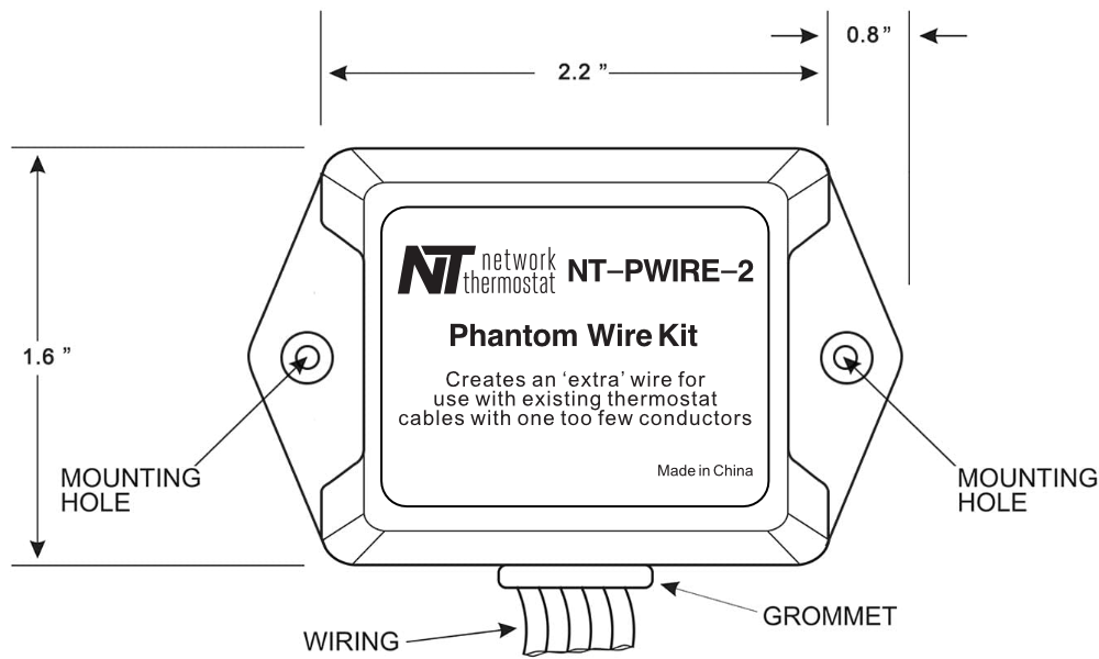
Step 1 – Location
The NT-PWIRE-2 should be mounted inside the HVAC unit in the control board area. The wires running from the device are 9 inches long, therefore the device must be placed within 6-7 inches of the thermostat connections at the HVAC terminal block. The NT-PWIRE-2 should not be installed in a location where the device or wiring may be exposed to the elements.
Step 2 - Wiring Requirements
The NT-PWIRE-2 wiring has the following requirements:
- All system wiring must be in compliance with all applicable local and national codes. All wiring should be color coded in conformance with standard recommendations.
- All wiring should be 18- 22-gage, unshielded wire. The recommended maximum distance between the NT-PWIRE-2 and the thermostat using an 18-gauge wire is 100ft. The maximum distance between the NT-PWIRE-2 and the thermostat using a 22-gauge wire is 36 ft.
Step 3 – NT-PWIRE-2 Wiring
WARNING
Before installing the NT-PWIRE-2, turn off all power to the unit. There may be more than one power disconnect.
DO NOT CONTINUE UNTIL VERIFYING THERE IS NO POWER AT THE HVAC AND THE THERMOSTAT, USING A VOLTMETER.
ONLY USE THIS DEVICE WITH A 24VAC THERMOSTAT. DO NOT USE WITH A LINE VOLTAGE THERMOSTAT.
- Remove all thermostat wires at the HVAC unit.
- Remove all thermostat wires from the old thermostat and install the new thermostat backplate.
AT THE THERMOSTAT - Connect the RED wire in the thermostat cable to the R terminal. (24VAC)
- Connect the GREEN wire in the thermostat cable to the C terminal. (24VAC common)
- Connect the WHITE wire in the thermostat cable to the W terminal. (Heat)
- Connect the DIODE ‘Y’ GREEN wire to the G terminal. (Fan)
- Connect the DIODE ‘Y’ YELLOW wire to the Y terminal. (Cool)
- Using a wire nut, connect the DIODE ‘Y’ BLUE wire to the YELLOW wire in the thermostat cable.
AT THE HVAC UNIT - Mount the NT-PWIRE-2 device close enough to reach the HVAC unit terminal strip.
- Connect the RED wire in the thermostat cable to the R terminal. (24VAC)
- Connect the GREEN wire in the thermostat cable to the C terminal. (24VAC common)
- Connect the WHITE wire in the thermostat cable to the W terminal. (Heat)
- Using a wire nut, connect the YELLOW wire in the thermostat cable to the BLUE wire coming from the NT-PWIRE-2 device.
- Connect the NT-PWIRE-2 RED wire to the HVAC unit R terminal.
- Connect the NT-PWIRE-2 GREEN wire to the HVAC unit G terminal.
- Connect the NT-PWIRE-2 YELLOW wire to the HVAC unit Y terminal.
- Connect the NT-PWIRE-2 BROWN wire to the HVAC unit C terminal.
TESTING
Before placing the thermostat on the backplate, perform the following tests to ensure all wiring is correct.
- Turn on 24VAC power. Using a voltmeter, confirm there is 24VAC between the R and C terminals on the thermostat backplate.
- Using a short wire jumper, connect between R and G on the thermostat backplate screw terminal. The FAN should turn on.
- Using a short wire jumper, connect between R and Y on the thermostat backplate screw terminal. The COOL/COMPRESSOR should turn on.
- Using a short wire jumper, connect between R and W on the thermostat backplate screw terminal. The HEAT should turn on.
Once all tests are complete and correct, install the thermostat onto the backplate.
Wiring Diagram
